+86 19720579616
+86 19720579616
Zalo
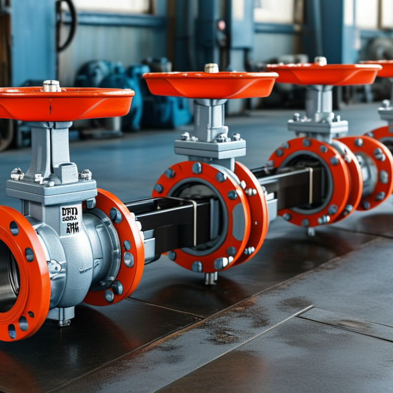
DIN Gate Valves are industrial isolation devices designed to control fluid flow through pipelines. Their name refers to German industrial standards, often associated with dimensions, pressure ratings, materials, and testing requirements. Inside the valve, a gate moves vertically between two seats. When fully raised, it creates a nearly straight flow path with limited resistance. When lowered, it blocks the passage and stops the medium.
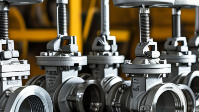
The mechanism is simple, but its performance depends on careful selection and installation. A handwheel turns a stem, which lifts or lowers the gate. Some designs use rising stems, while others keep the stem visually fixed. This difference matters in crowded plant areas. Operators can often identify valve position more easily with a rising stem. These valves work well for water, steam, oil, and compatible gases. They are usually poor choices for continuous throttling, because partial opening can damage the gate and seats.
Real service conditions deserve attention. Temperature, pressure, corrosion, and fluid contamination can change valve behavior. A valve may match the pipeline visually yet fail under operating stress. This guide explains construction, working principles, major types, and practical selection points for DIN Gate Valves. It also considers common maintenance mistakes, including incorrect tightening and neglected seat inspection. Standards and product data should be checked carefully. Requirements can vary by application. A drawing is not enough. Reliable decisions combine engineering calculations, manufacturer documentation, installation experience, and scheduled inspection. No valve is perfect. Its suitability must be proven in the actual system.
DIN gate valves are industrial isolation devices designed according to German Institute for Standardization requirements. They control fluid movement with a gate that travels vertically through the valve body. When fully open, the gate leaves a nearly straight passage. This design helps reduce pressure loss across pipelines. When closed, it blocks the flow firmly. Most gate valves are not suitable for regular throttling. Partial opening can cause vibration, erosion, and premature seat damage.
Their main purpose is reliable on-off service during maintenance, emergencies, or process changes. Engineers use them in water treatment, steam systems, chemical processing, and energy facilities. Common materials include cast iron, carbon steel, and stainless steel. The correct choice depends on pressure, temperature, fluid chemistry, and connection dimensions. Field experience shows that small installation errors can create serious leakage. Pipe alignment and gasket selection deserve careful inspection.
Tips: Confirm the applicable DIN requirements before ordering. Check the pressure rating and temperature range. Install the valve with enough clearance for stem movement. Do not force a stiff handwheel. A locked or corroded gate may indicate internal damage, not simple resistance. In practice, no valve choice is perfect; operators should review inspection records and service conditions regularly.
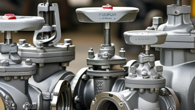
A DIN gate valve uses a sliding gate to control fluid flow through a pipeline. Its structure is designed for isolation, not precise throttling. The main pressure boundary includes the valve body and bonnet. The body contains the flow passage and supports the seats. The bonnet closes the upper chamber and guides the stem. Small details matter.
Inside, the gate moves vertically between two sealing seats. A wedge gate can press against both seats as the stem lowers. This creates a firm shutoff when fully closed. When the handwheel turns, the stem converts rotation into linear movement. Rising stems show valve position clearly above the bonnet. Non-rising stems save space but require reliable position markings. Stem packing limits leakage around the moving stem. A gasket seals the body-to-bonnet joint. These parts must match the service fluid, temperature, pressure, and pipe connection.
During maintenance, technicians inspect seat surfaces, stem threads, packing, and bonnet bolts. Clean alignment is essential. Even a strong body can fail if debris scores the seats. Gate valves usually perform best when fully open or fully closed. Partly open operation may cause vibration, erosion, and unstable flow. Field inspections often show that installation direction and pipe support are underestimated. The valve should not carry excessive pipe strain. DIN dimensional requirements can improve interchangeability, but they do not replace correct material selection or inspection. No design is perfect; field conditions can expose assumptions made on paper.
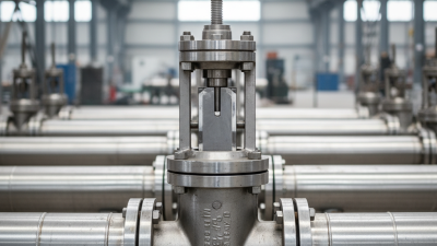
DIN gate valves use a movable wedge or parallel gate to open or stop fluid flow. When the handwheel turns the stem, the gate moves vertically away from or toward the valve seat. The main structural elements are the body, bonnet, gate, stem, seats, packing, and handwheel or actuator.
Nominal pressure classes: The chart shows common PN pressure designations used with DIN/EN valve and flange systems. PN values are nominal reference classes in bar; the permitted working pressure can vary with temperature, materials, valve design, and the applicable standard.
A DIN gate valve controls flow by moving a flat or wedge-shaped gate between two seats. Its dimensions and pressure ratings follow relevant DIN-based specifications. The valve body contains the flow passage, while the bonnet supports the stem and operating parts.
The process starts at the handwheel. Turning it rotates the threaded stem. The stem then lifts the gate vertically, away from the flow path. With the gate fully raised, fluid travels through a nearly straight passage. Pressure loss is usually low.
Turning the handwheel in the opposite direction lowers the gate. The gate presses against the seats and blocks the passage. Packing around the stem helps prevent external leakage.
The movement is simple. The sealing work is not. Operators should open the valve slowly and check for unusual resistance, vibration, or leakage. A valve forced against debris may damage its seats. That mistake is common.
Gate valves generally work best in fully open or fully closed positions, not as flow regulators. Partial opening can create turbulence, vibration, and faster wear.
In field inspections, confirming the flow direction, pressure rating, and stem movement matters before operation. Yet visual checks can miss internal seat damage. A pressure test may be necessary after maintenance, especially when the line carries hot or hazardous fluid. The exact result depends on installation quality, temperature, and the condition of the sealing surfaces.
What Are DIN Gate Valves and How Do They Work?
A DIN gate valve controls flow by lifting a flat or wedge-shaped gate from the passage. The gate moves vertically through a handwheel and stem. When fully open, it creates limited resistance. It is not designed for reliable throttling. Partial opening can cause vibration, erosion, and premature seat damage. Grand View Research estimated the global industrial valves market at USD 78.2 billion in 2022, reflecting demand across water, energy, and process industries.
DIN specifications help engineers match dimensions and operating conditions. DIN EN 1984 covers steel gate valves, while DIN EN 558 defines face-to-face dimensions for many industrial valves. DIN EN 1092-1 specifies common flange dimensions and pressure designations. These references reduce installation errors, but they do not guarantee safe performance. Pressure class, temperature, fluid chemistry, and testing records still require verification.
Material selection depends on service conditions. Carbon steel suits many oil, gas, and utility applications. Stainless steel performs better against corrosion and certain chemicals. Ductile iron is common in water systems because it balances strength and cost. Connection types include flanged, threaded, butt-welded, and socket-welded designs. Flanges simplify removal and maintenance. Threaded ends suit smaller lines, but seal quality can become a weak point. Welded connections provide compact, durable joints, although field repair becomes more difficult. In practice, a valve may meet every DIN dimension and still fail if the gasket, actuator, or installation torque is wrong.
| Data Dimension | Typical DIN Gate Valve Information | Technical Description | Selection or Application Notes |
|---|---|---|---|
| Basic Function | On/off isolation valve | A gate moves perpendicular to the flow path. When fully raised, the passage is substantially open; when fully lowered, the gate blocks the flow. | Best suited to fully open or fully closed service, rather than continuous throttling. |
| Flow Path | Generally straight-through | The open gate provides a relatively unobstructed flow path, typically resulting in low pressure loss compared with many regulating valve designs. | Useful in pipelines where low pressure drop and bidirectional isolation are important. |
| Operating Principle | Linear stem movement | Turning the handwheel rotates the stem. A threaded stem mechanism converts rotary motion into vertical movement of the gate. | The required number of turns depends on valve size, stem design, pressure, and actuator configuration. |
| Wedge Configuration | Solid wedge, flexible wedge, or split wedge | The wedge seals against seats located on both sides of the body. Flexible and split designs can accommodate limited thermal or alignment effects. | The appropriate wedge design depends on temperature, pressure, fluid properties, and required shutoff performance. |
| Stem Design | Rising stem or non-rising stem | A rising stem visibly moves upward during opening. A non-rising stem remains within the valve or bonnet while transferring motion to the gate. | Rising stems make position indication easier; non-rising designs can reduce installation height where space is limited. |
| Common Industrial Standard | DIN EN 1984 | Specifies requirements and tests for steel and cast iron gate valves used in industrial applications, within the scope and limitations of the standard. | Confirm the current edition and the valve material, pressure, temperature, and size range covered by the project specification. |
| Water Supply Standard | DIN EN 1074-2 | Covers requirements for isolating valves used in water-supply systems, including functional requirements and appropriate tests. | Use when the valve is intended for potable or general water-supply networks and verify any national or utility requirements. |
| Face-to-Face Dimensions | DIN EN 558 | Provides standardized face-to-face and center-to-face dimensions for certain industrial valves, including applicable gate valve series. | Check the specified series because short, standard, and long patterns may have different installation lengths. |
| Flange Dimensions | DIN EN 1092-1 | Defines circular steel flanges and their dimensions, including nominal size, pressure designation, bolt pattern, and sealing-face details. | The valve flange drilling must match the connected pipe flange in nominal size, pressure designation, facing, and bolt arrangement. |
| Nominal Size Range | Commonly DN 15 to DN 1000 or larger | DIN-based gate valves are manufactured in many nominal diameters, but the available range depends on body material, pressure class, end connection, and manufacturer design. | DN is a nominal reference and does not necessarily equal the exact internal or external diameter. |
| Pressure Designation | PN 6, PN 10, PN 16, PN 25, PN 40, and higher where applicable | PN is the nominal pressure designation used with many European valve and flange systems. Actual allowable pressure depends on temperature and material. | Do not treat PN as a universal working pressure at every temperature; always consult the pressure-temperature rating. |
| Body Materials | Ductile iron, cast iron, carbon steel, stainless steel, and alloy steel | The body material determines mechanical strength, corrosion resistance, temperature capability, weight, and compatibility with the service medium. | Select materials based on fluid chemistry, operating temperature, pressure, external environment, and applicable material standards. |
| Gate and Stem Materials | Coated ductile iron, stainless steel, carbon steel, or alloy steel | The gate must resist deformation and wear, while the stem must withstand torque, corrosion, and repeated operating cycles. | Stainless steel stems are frequently selected for improved corrosion resistance, especially in water and humid environments. |
| Seat Materials | Metal seated or resilient seated | Metal seats use metallic contact surfaces for demanding temperature or abrasive service. Resilient seats use elastomers to improve bubble-tight shutoff in suitable applications. | Elastomer compatibility, temperature limits, fluid cleanliness, and fire-safety requirements must be evaluated before selection. |
| Flanged Connection | Most common DIN connection type | The valve is bolted between pipe flanges using a gasket or other specified sealing arrangement. | Provides convenient installation and removal. Verify flange facing, bolt holes, gasket type, and pressure designation. |
| Butt-Weld Connection | Permanent welded pipeline connection | Weld ends are aligned with the pipe and joined by welding, producing a compact connection with no flange gasket. | Suitable for high-integrity systems, but installation requires qualified welding procedures and may complicate future removal. |
| Socket-Weld Connection | Small-diameter welded connection | The pipe fits into a socket in the valve end and is joined with a fillet weld around the connection. | Often used for smaller process lines; dimensional compatibility and welding requirements must be checked. |
| Threaded Connection | Female or male pipe threads | The valve connects directly to a threaded pipe or fitting using compatible thread forms and a suitable sealing method. | Common for smaller sizes and lower-risk services. Confirm thread standard, material, pressure rating, and leakage-control requirements. |
| Actuation Options | Handwheel, chainwheel, electric actuator, pneumatic actuator, or hydraulic actuator | Manual operation is common for smaller or infrequently operated valves. Powered actuators enable remote, automated, or high-torque operation. | Actuator sizing should consider breakaway torque, differential pressure, operating speed, duty cycle, and fail-position requirements. |
| Typical Applications | Water, wastewater, steam, hydrocarbons, chemicals, utilities, and industrial process lines | The valve isolates sections of a pipeline, equipment, tanks, pumps, and maintenance areas. | The service medium and operating conditions must be compared with the valve’s certified material and pressure-temperature limits. |
| Main Advantages | Low pressure loss, bidirectional isolation, and broad size availability | A fully open gate valve creates little obstruction, while the two-sided seating arrangement generally permits flow isolation in either direction. | The valve is especially useful where the pipeline normally operates fully open or fully closed. |
| Key Limitations | Slow operation, large installation space, and poor throttling suitability | The gate travels a relatively long distance, and partially open operation can cause vibration, turbulence, seat damage, and accelerated wear. | Use a globe, butterfly, ball, or control valve when regular flow regulation is required, subject to the system design. |
| Installation Checks | Alignment, flow direction, cleanliness, support, and access | The pipeline should be properly supported and aligned so that external loads do not distort the valve body or damage the seats. | Keep the valve accessible for operation and maintenance, and protect soft seats from debris during commissioning. |
| Maintenance Requirements | Stem inspection, packing adjustment, leakage checks, and functional cycling | Routine inspection helps identify stem corrosion, packing leakage, difficult operation, seat leakage, and actuator problems. | Maintenance intervals should be based on service severity, operating frequency, manufacturer instructions, and applicable plant procedures. |

Note: DIN-based requirements may be published as DIN, DIN EN, or DIN EN ISO standards. Always verify the current edition, product scope, pressure-temperature rating, materials, and project-specific requirements before procurement or installation.
DIN gate valves isolate pipeline flow by lifting a wedge from the fluid path. They are not designed for throttling. Partial opening can create vibration, seat wear, and damaging turbulence. During installation, confirm the valve’s DIN dimensions, pressure class, temperature rating, and flow direction. Although many gate valves work in either direction, the rising stem must remain accessible. Leave enough clearance for handwheel movement and future packing adjustment. Support heavy pipework separately. A valve should not carry the pipe’s weight.
Clean the flange faces carefully. Use a compatible gasket and tighten bolts in a cross pattern. After installation, perform a controlled pressure test under the applicable procedure. API 598 specifies shell and seat testing practices for industrial valves. For fugitive-emission checks, U.S. EPA Method 21 uses a 10,000 ppm screening threshold for many regulated components. That number is a warning, not a license to ignore smaller leaks. Inspect packing, bonnet joints, and flange edges with suitable detection equipment. Record torque, test pressure, and inspection dates.
Tips: Cycle the valve slowly and fully. Never force a stuck handwheel. Check for stem corrosion after cleaning or chemical exposure. Lubrication helps, but too much grease can hide packing failure. A 2023 process-safety review from an international engineering association noted that weak maintenance records often delay fault detection. That feels familiar in real plants. Labels also fade faster than expected, so verify line identity before any intervention.