
+86 19720579616
+86 19720579616
Zalo
Choosing Forged Steel Ball Valves starts with the actual service conditions, not the catalog headline. Pressure, temperature, fluid chemistry, and cycling frequency all affect valve selection. A valve installed on a hot process line faces different demands from one used for clean water. Small differences matter.
Grand View Research estimated the global industrial valves market at approximately USD 79.4 billion in 2023, with projected growth through 2030. That report covers industrial valves broadly; it does not measure forged steel ball valves alone. Still, it signals the scale of equipment decisions buyers make. For a specific valve, check the pressure-temperature rating, body and trim materials, connection type, seat design, and documented testing. API 608 and fire-test requirements such as API 607 may be relevant, depending on the application and project specification.
A practical selection also means checking what the paperwork can prove: material traceability, inspection records, and test results. Ask how the valve performs after repeated operation, not only how it looks on a clean bench. One caution: I could not verify a published quotation from a named forged-ball-valve specialist, so I will not invent one. That gap is worth acknowledging. A confident quote is no substitute for evidence. Compare the manufacturer’s stated limits with the actual operating conditions before choosing.
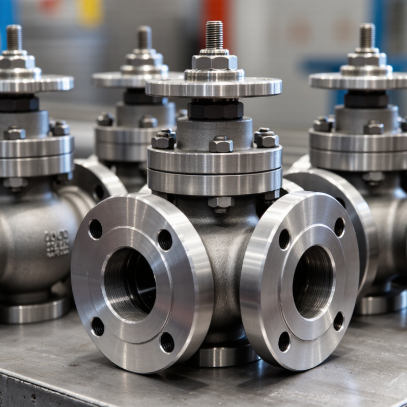
Forged steel ball valves begin with a pressure-containing body formed under heat and force. This process can limit internal voids, but forging alone does not guarantee quality; material selection, heat treatment, and machining matter too. In a typical floating-ball design, upstream pressure pushes the ball against the downstream seat to seal flow. Trunnion-mounted designs support the ball at both ends, helping manage larger sizes or higher operating loads. A quarter-turn stem rotates the ball between open and closed positions. Simple motion. But stem sealing and seat wear still need attention.
Look inside the assembly: the ball’s bore aligns with the pipe when open, while solid ball surfaces block flow when closed. Seats, stem, body joints, and seals all affect leakage and service life. API 598 specifies minimum shell-test holding times by valve size; for NPS 2 and smaller, the minimum is 15 seconds. This is a useful inspection benchmark, not proof of performance in every operating condition. Check the applicable test requirements, pressure rating, temperature range, and fluid compatibility before choosing a valve. A heavier body may feel reassuring, yet it is not automatically the better choice. Verify the actual design and test records.

A simplified component count for a typical floating-ball valve. Exact construction varies by valve design and size.
The ball rotates a quarter turn (90°): the bore aligns with the pipeline to allow flow and turns across it to shut off flow. Seats seal against the ball, while the stem transfers motion from the handle or actuator. When selecting a valve, check the pressure and temperature ratings, materials, end connections, and intended service.
A forged steel ball valve should be selected for its full operating envelope, not pipe size alone. Record normal and upset pressure, temperature extremes, fluid composition, solids, and required shutoff performance. ASME B16.34-2020 assigns pressure-temperature ratings by material and valve class; a Class 600 label is not a universal pressure limit. Ratings change with material and temperature. ASTM A105/A105M specifies minimum tensile strength of 70 ksi and yield strength of 36 ksi for carbon-steel forgings, but these figures do not replace the assembled valve’s rating. Check the nameplate and certified data. Small details matter.
For media, check corrosion, erosion, viscosity, and seal compatibility at actual operating conditions. Dry gas, wet steam, and abrasive slurry may require different seats, even at the same pressure. For flow, gather minimum, normal, and peak rates before choosing a port size. ISA 75.01.01-2012 defines Cv using water at 60°F. Cv is the US gallons per minute flowing with a 1 psi pressure drop. Treat this as a sizing reference, not a direct prediction for compressible gas or flashing liquid. Not just pressure. Confirm inlet and outlet conditions with a qualified engineer; those assumptions are easy to misread. Record uncertainties in the specification, too.
| Selection Factor | Information to Define | How It Affects Valve Selection | Practical Selection Check |
|---|---|---|---|
| Operating pressure | Normal and maximum operating pressure, including start-up, shutdown, and credible pressure surges. | The valve pressure class must suit the maximum design conditions. ASME Class 150, 300, 600, 900, 1500, and 2500 are class designations—not universal pressure values. | Confirm the pressure rating against the applicable pressure–temperature rating table for the specified body material and governing standard. Do not select by class number alone. |
| Temperature | Minimum and maximum fluid and ambient temperatures, plus the duration and frequency of temperature extremes. | Temperature affects the allowable pressure rating, body material suitability, seat performance, and sealing capability. | Check the pressure–temperature limits for the body material and confirm that the seat, seals, and other trim materials are suitable across the full temperature range. |
| Process media | Fluid composition, phase, cleanliness, corrosive components, solids, viscosity, and any applicable service requirements. | Media compatibility influences body, ball, stem, seat, and seal materials. Abrasive particles or deposits may affect shutoff and operating torque. | Provide the complete fluid composition where possible. For sour service, determine whether NACE MR0175/ISO 15156 requirements apply and specify them when required. |
| Flow and capacity | Required flow rate, upstream and downstream pressures, pressure drop, and whether the valve will operate fully open or modulate flow. | Port size and flow path affect capacity and pressure loss. A full-port valve generally offers a more direct flow path than a reduced-port valve of the same nominal size. | Size using the process design conditions and the manufacturer’s published flow coefficient (Cv or Kv) data. Do not assume the valve nominal size alone provides adequate capacity. |
| Valve size and end connections | Required nominal pipe size, pipe schedule, connection type, and applicable dimensional standard. | Forged steel ball valves may be supplied with threaded, socket-weld, or butt-weld ends, depending on size, pressure class, and design. | Verify end-connection dimensions and compatibility with the piping specification. For welded ends, confirm material, weld preparation, and installation requirements. |
| Body and trim materials | Required material grades for the pressure-containing body and wetted components, based on design conditions and fluid compatibility. | Forged body materials are selected for the required strength, temperature range, and service environment. Ball, stem, and seat materials must also suit the media and duty. | Specify material grades and any required material test documentation in the purchase specification. Confirm compatibility for every wetted component, not only the body. |
| Seat and shutoff requirements | Required leakage performance, frequency of operation, differential pressure during closure, and presence of solids or abrasive particles. | Soft seats can provide tight shutoff in suitable conditions; metal seats may be considered for demanding temperature, wear, or service conditions. Actual capability depends on the valve design. | State the required shutoff or leakage criterion and applicable test standard. Confirm the seat type, allowable differential pressure, and operating torque for the specified service. |
| Operation and actuation | Manual or actuated operation, operating frequency, available power, control requirements, and fail position where applicable. | Actuator sizing depends on valve torque under the actual pressure, temperature, and media conditions. Frequent cycling or throttling may require a different design from simple isolation duty. | Provide the required operating conditions and control details. Confirm actuator torque margins and whether the application requires on/off isolation or flow control. |
| Applicable standards and testing | Project codes, design standard, inspection requirements, pressure testing, fire-safe requirements, and emissions criteria. | Applicable standards depend on the valve type and service. ASME B16.34 covers valve pressure–temperature ratings and design-related requirements; other standards may apply to specific valve types or applications. | List the required standards and editions in the specification. Where required, identify fire testing, shell and seat testing, fugitive-emissions qualification, and inspection documentation explicitly. |
| Installation and maintenance | Available space, access for operation, piping loads, orientation constraints, and maintenance or replacement needs. | Installation details affect access, actuator clearance, connection selection, and the ability to inspect or service the valve safely. | Check the valve dimensions and installation instructions against the piping layout. Confirm flow direction or orientation requirements for the selected design. |
Selection note: Final valve selection should be based on the project design conditions, applicable codes, and the manufacturer’s certified pressure–temperature, flow, materials, and test data. The checks above are a specification guide, not a substitute for engineering review.
When comparing forged steel ball valves, start with the fluid and temperature, not the catalog headline. ASTM A105/A105M specifies a 70 ksi minimum tensile strength for carbon-steel forgings; strength alone does not predict corrosion resistance. For wet, chloride-bearing service, evaluate stainless-steel grades such as forged 316 against the actual chemistry and temperature. ASME B16.34 pressure-temperature tables help check allowable ratings by material group and class. Use the specified design conditions, not just the line’s normal pressure. A small mismatch matters.
Port design changes both flow and valve size. A full-port ball offers a larger passage for pigging or solids, while a reduced-port design can be more compact. Do not assume every reduced port causes the same pressure loss; compare the manufacturer’s flow coefficient, Cv, at the expected operating point. End connections shape installation and maintenance: threaded ends suit some small-bore lines, socket welds create compact welded joints, and butt welds integrate into larger piping. Flanged ends simplify removal, but add face, gasket, and bolt checks. ASME B16.5 covers flange dimensions and pressure classes; ASME B16.25 covers butt-welding ends. I still verify the piping class against the valve drawing. Drawings can reveal details catalogs miss.
Checking Standards, Testing, and Safety Features
Check the pressure class, temperature range, end connections, and service fluid against the project specification. ASME B16.34 provides pressure-temperature ratings for valves, while API 598 sets out inspection and pressure-testing requirements. Under API 598, the tabulated shell-test pressure is typically 1.5 times the valve’s pressure rating at 100°F; confirm the applicable table for the exact class and size. Look closely.
Request traceable material records and test results tied to the valve’s serial or heat number. During inspection, check the body marking, stem movement, seat leakage record, and whether the test medium matches the specified procedure. A certificate is useful, but it cannot show how the valve was stored or handled afterward. That gap deserves attention.
For fire-risk service, ask whether the design has qualification to API 607 or ISO 10497; a test qualification is not a promise of zero leakage in every fire. Confirm stem retention, antistatic provisions, and the specified fire-safe construction. Ask for the test report, not just a brochure claim. If operating conditions are unusual, have a qualified engineer review the ratings and test plan before purchase.
Choosing a forged steel ball valve starts with the line, not the catalog size. Check pipe diameter, flow rate, pressure drop, temperature, and fluid condition. A full-bore valve may reduce restriction in a high-flow line, while a reduced-bore design can suit some space or cost constraints. Compare the valve’s flow coefficient with the system requirement; matching nominal pipe size alone is not enough. Real installations are rarely textbook-clean. A small change in viscosity or operating pressure can affect performance.
Actuation should match both operating conditions and how often the valve moves. For a hand lever, confirm that operators can reach it safely and provide enough clearance for a full turn. For powered actuation, size the drive using the valve’s required torque, including pressure and seat friction.
Consider the desired response if power or air supply is lost. That detail matters. Maintenance needs deserve the same attention: allow room to inspect the stem and connections, and check whether seats and seals can be serviced without awkward access.
Dirt, frequent cycling, and temperature swings can increase wear. A tidy specification may still miss a cramped installation or an unexpectedly sticky valve, so verify assumptions against the actual line and operating routine.