
+86 19720579616
+86 19720579616
Zalo
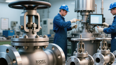
A DIN bellows sealed gate valve is designed to control or isolate flow while limiting leakage around the moving stem. Its metal bellows forms a flexible barrier between the process fluid and the external packing area. As the handwheel turns, the stem moves the gate, while the bellows compresses or extends with that motion. The design is often considered where emissions control or protection from hazardous, corrosive, or high-purity media matters. Small details matter.
Din Bellows Sealed Gate Valves are not defined by the bellows alone. Buyers and engineers also need to check the applicable DIN design requirements, pressure rating, temperature range, body and trim materials, and end connections. A valve that fits the pipe may still be unsuitable for the service. For example, a hot process line can place very different demands on bellows fatigue life than a cool utility line. The product datasheet and the operating conditions should be reviewed together.
This guide explains the valve’s main components, how its sealing arrangement works, and where it may be appropriate. It also considers practical limits, including bellows damage, installation stress, and the need for inspection. No metal barrier lasts forever. That point can be easy to overlook when a valve appears leak-tight during initial testing. DIN specifications and manufacturer documentation help establish a clear basis for selection, but they do not replace careful application review. The right choice depends on the fluid, the operating cycle, and the consequences of leakage.
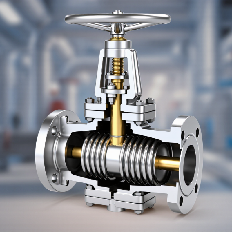
A DIN bellows-sealed gate valve is an isolation valve that uses a metal bellows to seal the moving stem from the surrounding atmosphere. The gate moves across the flow path, opening or closing the line. DIN identifies a relevant German standards framework; the exact dimensions and requirements depend on the standard specified for the valve. The bellows is typically welded between the stem and bonnet, creating a flexible barrier that helps prevent process fluid from escaping along the stem. That seal is the key distinction.
This design is useful where stem leakage needs tight control, such as lines carrying hot water, steam, or certain corrosive fluids. Picture a valve installed above a warm pipe: repeated turning moves the stem, while the bellows flexes with it. It is a barrier, not a throttle. Gate valves are generally intended for open-or-closed service, not precise flow adjustment. Bellows can also fatigue after repeated movement or pressure and temperature cycles, so selection should account for operating conditions and inspection needs. The term “DIN valve” can be confusing; the standard, pressure rating, materials, and end connections still need checking against the actual system.
A DIN bellows-sealed gate valve has several parts working together to control flow and limit leakage. The body contains the process fluid and provides the pressure boundary. Inside, the gate moves between seats to stop or permit flow; it is not intended for precise throttling. The bonnet supports the stem assembly and encloses the upper opening. A metal bellows is welded between the stem and bonnet, flexing as the stem travels while blocking a direct leak path. That thin metal section does demanding work.
The packing around the stem usually serves as a secondary seal if the bellows fails. The handwheel or actuator supplies movement, while the stem transfers it to the gate. Seat surfaces must align closely; grit or wear can cause leakage past the closed gate, even when the bellows remains intact. The IEA’s Global Methane Tracker 2024 estimated fossil-fuel operations emitted about 120 million tonnes of methane in 2023. That figure covers the wider sector, not gate valves alone, but it shows why controlling equipment leaks matters. ISO 15848-1 provides a test framework for fugitive emissions from industrial valves. In practice, weld quality, installation, and maintenance still matter. A drawing cannot prove field performance.
This chart groups eight typical components by their primary role, with two components in each group: the body and bonnet contain pressure; the gate and seats control and shut off flow; the bellows and stem packing provide stem sealing; and the stem and handwheel or actuator transmit operating force. The bellows provides the primary stem seal, while packing commonly serves as a secondary seal.
What Is a DIN Bellows Sealed Gate Valve?
How the Valve Opens, Closes, and Seals
A DIN bellows sealed gate valve uses a moving gate to start or stop flow through a pipeline. Turning the handwheel moves the stem, lifting the gate clear of the flow path or lowering it onto the seats. In many designs, the gate is wedge-shaped. When fully open, it leaves a largely unobstructed passage. This valve is designed for on-off service, not precise flow control.
The bellows is a flexible metal component joined between the stem and bonnet. As the stem travels, the bellows expands or compresses while forming a barrier around the stem. This helps prevent process fluid from escaping through the stem packing area. When closing, the gate meets the seats and blocks flow; the bellows continues to isolate the moving stem from the fluid. Small movements matter.
DIN refers to dimensional and technical standards used in the valve’s design, but details can vary by specification and application. A bellows is not indestructible. Repeated cycling, pressure changes, or unsuitable temperatures can shorten its service life. Inspect the valve for external leakage, difficult handwheel movement, and signs of corrosion. A slight hesitation may be worth checking, even if the valve still turns.
| Part or Stage | What Happens | How It Opens | How It Closes and Seals |
|---|---|---|---|
| Valve body and bonnet | The body contains the flow passage, while the bonnet encloses the stem and connects to the body. | When the gate is raised clear of the flow path, fluid can pass through the body. | When the gate is lowered onto its seats, it blocks the flow passage. Body and bonnet joints are sealed according to the valve design. |
| Handwheel or actuator | The operating device turns or moves the stem to position the gate. | On a typical manually operated valve, turning the handwheel counterclockwise raises the gate. | Turning the handwheel clockwise typically lowers the gate. Operating direction should be confirmed from the valve markings or instructions. |
| Stem | The stem transmits movement from the operating device to the gate. | As the stem moves upward, it lifts the gate away from the seats. | As the stem moves downward, it presses the gate into the closed position. Stem arrangement and movement depend on the design. |
| Gate and seats | The gate is the closure element; the seats are the surfaces it contacts to stop flow. | The gate moves out of the flow path, providing a relatively direct passage when fully open. | The gate contacts the seats to shut off flow. Gate and seat designs can vary, so a gate valve should not normally be used for throttling. |
| Metal bellows | A flexible, welded metal bellows surrounds the moving stem section and forms a pressure boundary between the process fluid and the outside environment. | The bellows extends or compresses as the stem moves, while remaining attached at its end connections. | Its welded construction helps prevent process fluid from escaping along the stem during normal operation. Bellows condition and operating limits must be maintained. |
| Stem packing or secondary seal | Some designs include packing above the bellows as a secondary stem seal. | It remains around the moving stem as the valve is operated. | If fitted, it can provide an additional sealing barrier, including in the event of bellows failure. Arrangement and maintenance requirements vary by design. |
| Fully open position | The gate is lifted clear of the seats and flow path. | The valve permits flow through the body with relatively low obstruction when correctly sized and fully open. | The gate is not sealing against the seats in this position; the bellows continues to isolate the stem opening from the process fluid. |
| Fully closed position | The gate is seated across the passage. | Not applicable; the gate is in its shut-off position. | The gate-to-seat contact stops flow through the valve. The bellows provides stem sealing, not the primary shut-off between the inlet and outlet. |
Note: “DIN” refers to German standardization. Dimensions, pressure-temperature ratings, materials, end connections, gate design, and sealing details depend on the applicable standard and the specific valve specification. Check the manufacturer’s documentation before selection or operation.
A DIN bellows-sealed gate valve combines a rising or non-rising stem with a welded metal bellows that limits leakage around the stem. DIN EN 1984 covers steel gate-valve design, while EN 12266-1 specifies pressure testing and leakage acceptance criteria. These standards do not create one universal pressure rating for every bellows valve. Check the valve’s certified design documents.
Material choice sets practical limits. Carbon steel suits many steam and process lines; stainless steel is often selected when corrosion resistance matters. The relevant pressure-temperature tables in ASME B16.34 show why a nominal pressure class is not a fixed allowable pressure: the permitted value changes with material group and temperature. Hot steam can reduce the allowable pressure substantially. Check the exact material, end connection, and temperature rating, not just the PN or class marking. Small detail, big consequence.
Operating limits also depend on the bellows alloy, cycle count, fluid chemistry, and pressure transients. Bellows fatigue data and cycle testing deserve review when a valve will cycle often. A static rating alone may miss that risk. EN 12266-1 provides test procedures, but it does not predict service life under every plant condition. Ask for pressure-temperature ratings, test records, and stated cycle assumptions. The paperwork can be imperfect; compare it with actual line temperatures and startup conditions.
A DIN bellows sealed gate valve uses a metal bellows around its stem to reduce leakage along the moving stem. The gate provides isolation, while the bellows separates the stem from the process fluid. This design is useful where fugitive emissions or fluid loss must be tightly controlled.
Common applications include chemical transfer, steam lines, heat-transfer systems, and services involving costly or hazardous fluids.
The IEA’s Global Methane Tracker 2024 estimates that energy operations emitted nearly 120 million tonnes of methane in 2023. This sector-wide figure is not specific to valves, but it underscores why leakage control matters. Small leaks add up.
Selection depends on pressure, temperature, fluid compatibility, bellows material, and operating frequency. Check the valve’s pressure-temperature rating and documented bellows cycle life, especially where frequent operation is expected. Gate valves generally suit isolation, not continuous throttling; partial opening can cause wear. Installation space and end connections matter, too. A datasheet may look complete, yet actual cycling conditions are easy to underestimate.